Overland Engineering and Logistics Co
Get Consultation
+1(314)377-4890
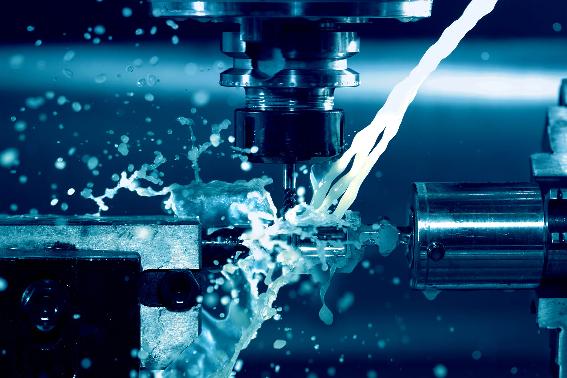
CNC Machining Machinery
We prioritize producing parts based on your 3D models
Here is a step-by-step process of manufacturing a camera chamber at Overland, starting from the initial 3D design to the final part using CAM software, CNC turning, and milling machines.
1,Verifying and validating drawings
Upon order confirmation, we have received and reviewed over ten thousand 2D and 3D CAD drawings from clients. Our thorough checking process ensures that any issues with opening the drawing files or other obvious problems are promptly addressed before production begins:
- If a part falls outside the capabilities of Overland, we will provide a “no quote” response.
- We offer suggestions for design improvements to optimize production and reduce costs without compromising functionality.
- We strive to provide you with the quickest possible lead time for delivery when issuing a quote.
2,Creating CNC instructions
Our skilled CNC programmers utilize Mastercam, a PC-based CAD/CAM software, for efficient and rapid turning and milling operations. Throughout this stage, we continuously explore opportunities to optimize the design for enhanced production efficiency.
| How to Create a Custom CAD Drawing
The Process of Generating a CAD Drawing
CAD software has revolutionized engineering modeling in industries such as automotive, aerospace, reverse engineering , PCB design, animation design, industrial design, and architectural design. Here are the general steps involved in creating 2D and 3D CAD drawings using CAD software:
- Conceptualize the design.
- Select the appropriate CAD software.
- Create a new drawing and set parameters.
- Sketch and draft the design.
- Apply dimensions and constraints.
- Create 3D models.
- Fine-tune and edit the design.
- Assemble components if needed.
- Assign materials and textures.
- Generate realistic renderings or animations.
- Create technical drawings for documentation.
- Save the CAD drawing in the desired file format.
How to Get CAD Software?
CAD software is a vital tool in CNC machining service projects, offering powerful capabilities. An ideal CAD program should enable both 2D drawing and 3D modeling. However, selecting the best modeling software across different market sectors can be challenging due to the variety of features available. The key elements of good CAD software include:
- Comprehensive functionality
- User-friendly interface
- Accurate and precise modeling
- Compatibility with various file formats
- Efficient editing and modification tools
- Robust rendering and visualization capabilities
- Collaboration and sharing features
- Adequate technical support and updates
There are numerous free CAD software options available for both personal and professional modeling needs. If you have any questions about CAD software applications, feel free to reach out to us via email.
*Ref 1. Computer-aided design-Wikipedia
What OVERLAND Need for Quote
Before submitting an RFQ (Request for Quote) to us, it is essential that you have your own 2D and 3D CAD drawings to clearly represent your project. Alternatively, if you have a physical sample and require reverse engineering, we can assist you in that process.
In addition to the 2D and 3D CAD drawings, it is the customer’s responsibility to provide detailed information for the RFQ project. Based on our core services, the required information can be categorized as follows:
1, CNC Machining Service
- Material
- Surface Finish
- Batch quantity / Annual quantity
- Other important notices for manufacturer
2, Other Services
– Stamping
- Material, including thickness
- Surface Finish
- Batch quantity / Annual quantity
- Other important notices for manufacturer
– Plastic Injection
- Material
- Color
- Surface texture
Batch quantity / Annual quantity - Surface region allowed for inlet, venting, ejector pins
- Other important notices for manufacturer
For long-term and large quantity production, we highly recommend utilizing plastic injection molds with multiple cavities. While this may incur higher tooling costs upfront, it results in significantly lower unit prices per part. With multiple cavities, more parts can be produced in a single shot, improving efficiency and reducing overall production costs.
– Die Casting
- Material
- Surface Finish
Batch quantity / Annual quantity - Surface region allowed for inlet, venting, ejector pins
- Other important notices for manufacturer
What is Swiss machine ?
Swiss machines , also known as Swiss lathes or Swiss automatic lathes, are highly efficient due to their ability to perform simultaneous machining operations. This capability allows multiple tools to work on the workpiece simultaneously. Swiss machining operates by applying a Z-axis feed to the bar stock through an automated chuck. This chuck grips the feedstock and advances it into the machine’s operational area. The bar stock extends into the tooling area just enough to meet the operational needs for a single part. A rotating support or guide bushing supports the bar stock immediately behind the tool application area.
In contrast, a manual or CNC lathe presents the workpiece in a fixed-position chuck that rotates but does not move along the Z-axis. For longer components, a tailstock can provide additional support, reducing bending from cutting forces. However, in a Swiss lathe, the workpiece can rotate and move back and forth along the Z-axis while various tools simultaneously cut different features of the part. This multi-zone operation is a key advantage of Swiss lathes, as traditional lathes can only operate in a single zone at a time. Additionally, the Z-axis positioning control and powered tool posts enable Swiss machines to perform milling operations, which do not involve turning.
| Billet Cutting
Having well-prepared raw materials is crucial for efficient mass production and cost reduction. Our billet shearing machine can handle billet sizes ranging from 100mm square to 300mm square, enabling precise and efficient cutting. Billet cutting is a necessary step before CNC milling, as well as for manufacturing CNC turning components with rods larger than 65mm in outer diameter.
| CNC Programming
To ensure ease, productivity, and profitability in our fabrication process, we rely on the PC-based CAD/CAM software Mastercam. It enables us to streamline design, engineering, operation, programming, and machining, saving valuable time and maximizing efficiency in turning-milling fabrication.
| Versatile Machining Services
Design and Manufacturing Experts
We are dedicated to delivering the highest quality parts and products to our clients. As a one-stop shop, we provide comprehensive services for machined parts, tooling for plastic injection, die casting, and stamping. Our R&D team possesses extensive manufacturing experience and knowledge, resulting in exceptional machining craftsmanship that our clients admire.
As a leading CNC precision manufacturing service provider with over 30 years of success, we offer world-class expertise. Simply send us your parts’ CAD drawings for a free quote, and our skilled engineers will review your project to ensure its manufacturability.